
Table of Contents
RPi Hardware
Introduction

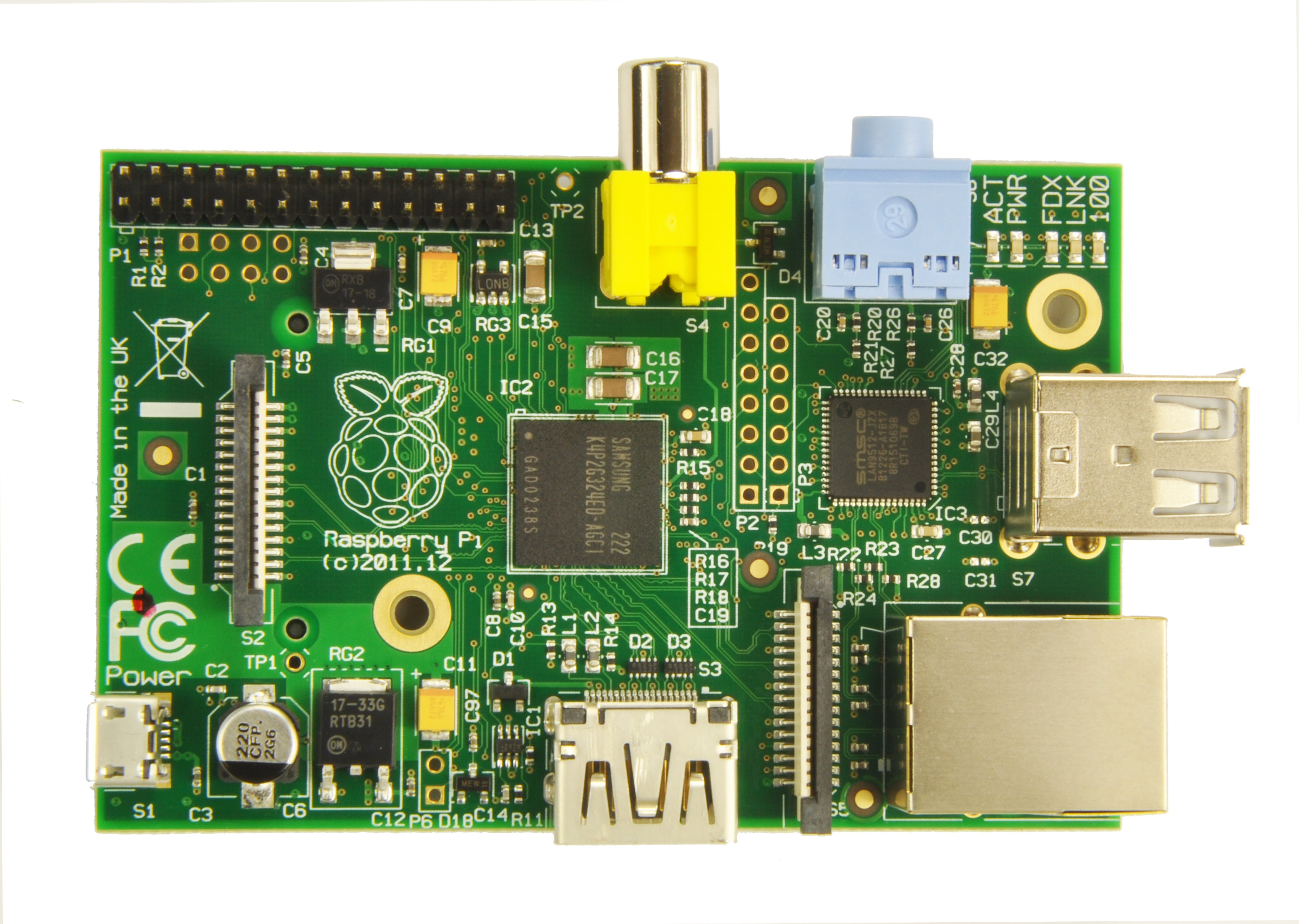
| thumb | right | The unpopulated Rpi bèta board The first product introduced from the Raspberry Pi foundation was the size of a credit card, and was designed to plug into a TV or HDMI monitor. The foundation has kept this form factor over the revisions but have increased the performace while keeping the relavively low price point. The Rpi Low-level peripherals | GPIO pins on each board allow the use of optional Rpi expansion boards | expansion boards. The current price for the the model A+ is $20, while the model B+ and Raspberry Pi 2 are both $35 each.
Several different minor hardware versions/revisions RaspberryPi Boards have been found probably from different assembly lines. Try to identify your board for better troubleshooting and update it if you have one which is not mentioned.
Those who are looking to set up a Raspberry Pi for the first time, see RPi Hardware Basic Setup.
Raspberry Pi Hardware History
There have been six major board revisions of the Raspberry Pi board.
To view the full history on the hardware of the Raspberry Pi check out the Rpi_HardwareHistory | Rpi Hardware History.
Specifications
{]] | class="wikitable" ! ! Model A ! Model B ! Model A+ ! Model B+ ! Raspberry Pi 2 ! Raspberry Pi 3 ! Raspberry Pi Zero | - | //www.raspberrypi.org/faqs</ref> | US$25 Ext tax (GBP £16 Exc VAT) | US$35 Ext tax (GBP £22 Exc VAT) | //www.raspberrypi.org/raspberry-pi-model-a-plus-on-sale/</ref> | US$35 Ext tax (GBP £22 Exc VAT) | //www.raspberrypi.org/raspberry-pi-2-on-sale/</ref> | US$35 Ext tax (GBP £22 Exc VAT) | //www.raspberrypi.org/blog/raspberry-pi-zero/</ref> | - | <ref name="faq" /> | colspan="4" | Broadcom BCM2835 (CPU + GPU. SDRAM is a separate chip stacked on top) | Broadcom BCM2836 | Broadcom BCM2837 | Broadcom BCM2835 | - | CPU | colspan="4" | MHz ARM11 ARM1176JZF-S core | 900MHz quad-core ARMv7 Cortex-A7 | 1.2GHz 64-bit quad-core ARMv8 Cortex-A53 | 1000MHz Low Power ARM1176JZF-S | - | GPU | colspan="5" | Broadcom VideoCore IV, OpenGL ES 2.0,OpenVG 1080p30 H.264 high-profile encode/decode, 250 MHz | colspan="1" | Broadcom VideoCore IV, OpenGL ES 2.0,OpenVG 1080p60 H.264 high-profile encode/decode, 400 MHz | colspan="1" | Broadcom VideoCore IV | - | Memory (SDRAM)iB | MiB on 29 Feb 2012) | MiB (since 15 Oct 2012) | MiB | MiB | colspan="2" | MiB | MiB | - | USB ports | 1 USB 2.0 (provided by the BCM2835) | 2 USB 2.0 (via integrated USB hub in LAN9512) | 1 USB 2.0 (provided by the BCM2835) | colspan="3" | 4 USB 2.0 (via integrated USB hub in LAN9514) | 1 Micro USB OTG (On The Go) | - | <ref name="faq" /> | colspan="2" | Composite video | Composite RCA, HDMI (not at the same time) | colspan="4" | HDMI | Composite video requires 4 Pole Adapter | HDMI, Composite video via unsoldered 2-pin header | - | <ref name="faq" /> | colspan="6" | TRS connector | 3.5 mm jack, HDMI | Multi-Channel HD Audio over HDMI | - | Audio inputs | colspan="7" | None, but a USB mic or sound-card could be added | - | Onboard Storage | colspan="2" | Secure Digital | SD / MMC / SDIO card slot | colspan="5" | Micro Secure Digital / MicroSD slot | - | <ref name="faq" /> | None | colspan="1" | 10/100 wired Ethernet RJ45 | None | colspan="2" | 10/100 wired Ethernet RJ45 | colspan="1" | 10/100 wired Ethernet RJ45, integrated 802.11n Wi-Fi & Bluetooth 4.1 | None | - | Low-level peripherals | colspan="2" | Sad about removal of I2S. Why was this change made | colspan="4" | Sad about removal of I2S. Why was this change made | 40 General Purpose Input/Output (GPIO) pins, Serial Peripheral Interface Bus (SPI) (unpopulated) | - | <ref name="faq" /> | colspan="7" | None | - | Power ratings | W) <ref name="faq" /> | W) | 600mA up to 1.2A @ 5V | colspan="2" | //www.element14.com/community/community/raspberry-pi/raspberry-pi-bplus | 800mA (4.0 W), up to 2.5A | 160mA rating | - | <ref name="faq" /> | colspan="7" | V (DC) via Micro USB type B or GPIO header | - | Size | 85.0 x 56.0 mm x 15mm | 85.0 x 56.0 mm x 17mm | 65.0 x 56.0 mm x 12mm | 85.0 x 56.0 mm x 17mm | 85.0 x 56.0 mm x 17mm | 85.6 x 56.5 mm x 17mm | 65.0 x 30.0 mm x 5mm | - | Weight | 31g | 40g | 23g | 40g | 40g | 45g | 9g | Raspi-Model-AB-Mono-2-699x1024.png | 400px | thumb | right | A diagram denoting the places of the different components on the Raspberry Pi, made by Paul Beech, edited to show 256 MB RAM for both boards (Provisional - some of the expansion interfaces won't be available on production boards) (PCB IDs are those of the Model B Beta board)
- SoC: Broadcom BCM2835 media processor (datasheet, BCM2835 datasheet errata, RPi_BCM2835_Pinout | unofficial pinout, BCM2835_registers | BCM2835 Register documentation - based on GPU source code) system-on-chip featuring:
- CPU core: ARM1176JZF-S ARM11 core clocked at 700 MHz; ARM VFP. The ARM11 core implements the ARMv6 Architecture. For details on ARM instruction sets and naming conventions, see ARM architecture and List of ARM microprocessor cores.
- GPU core: a Broadcom VideoCore IV GPU providing OpenGL ES 1.1, OpenGL ES 2.0, hardware-accelerated OpenVG 1.1, Open EGL, OpenMAX and 1080p30 H.264 high-profile decode. There are 24 GFLOPS of general purpose compute and a bunch of texture filtering and DMA infrastructure. Eben worked on the architecture team for this and the Raspberry Pi team are looking at how they can make some of the proprietary features available to application programmers
- DSP core: There is a DSP, but there isn't currently a public API (Liz thinks the BC team are keen to make one available at some point) thread
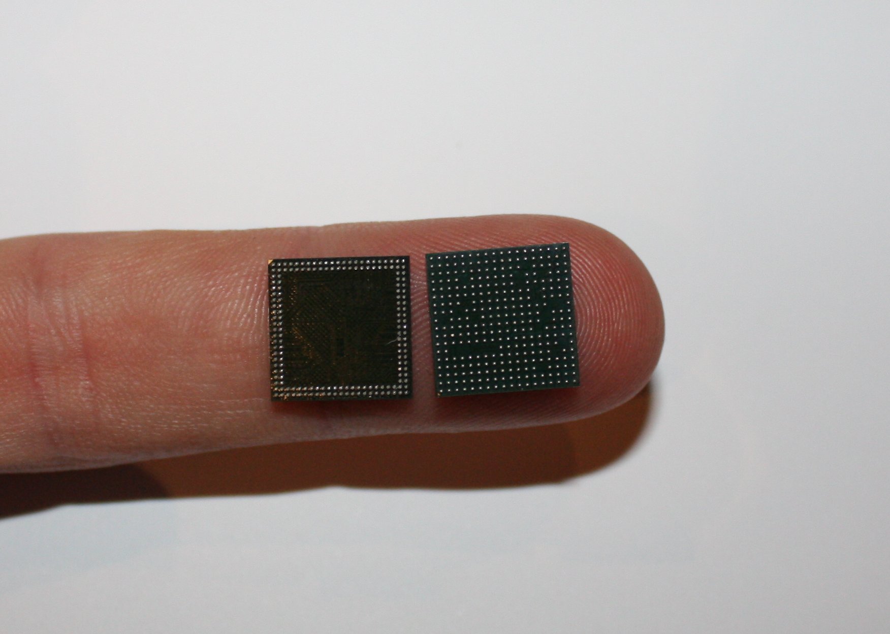
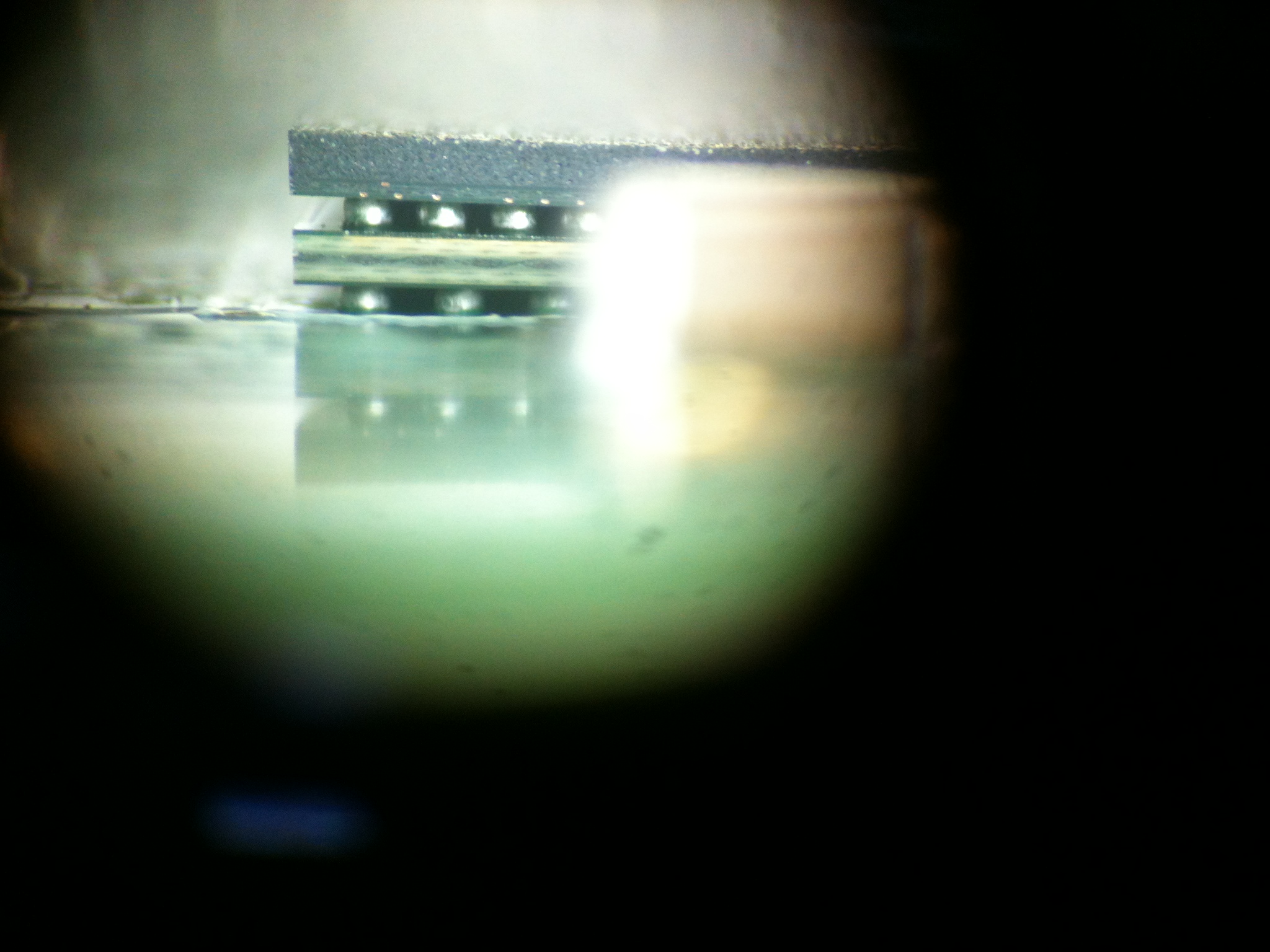
- 256 MiB of (Hynix MobileDDR2 or Samsung Mobile DRAM) SDRAM (or 512 MB Mobile DRAM on later boards). The RAM is physically stacked on top of the Broadcom media processor (package-on-package technology). Here is a photo of the SDRAM (left) and BCM2835 (right) ball grid arrays on JamesH's finger. You are looking at the bottom side. The BCM2835 top side has a land grid array which matches the SDRAM ball grid array. Here is a highly magnified side view of the SDRAM stacked on top of the BCM2835 stacked on top of the PCB PoP stack (you can see why its job can only be done by robots!).
- LAN9512 (Data Brief ]] | Auto-MDIX Wikipedia:Auto-MDIX]</ref> ** 2x USB 2.0 * S1: Micro USB power jack (5 V - Power Only) * S2: [http://www.mipi.org/specifications/display-interface DSI] interface. 15-pin surface mounted flat flex connector, providing two data lanes, one clock lane, 3.3 V and GND. * S3: HDMI connector providing type A HDMI 1.3a out * S4: Composite Video connector: RCA * S5: MIPI [http://www.mipi.org/specifications/camera-interface CSI-2] interface. 15-pin surface mounted flat flex connector. * S6: Audio connector: 3.5mm stereo jack (output only) * S8: SD/MMC/SDIO memory card slot (underside) * S7: Either 1x USB 2.0 '''(Model A)''' 2x USB 2.0 '''(Model B)''' * P1: 26-pin (2x13) 2.54 mm header expansion, providing: see [[Rpi_Low-level_peripherals | Low-level peripherals
- 8 General_Purpose_Input.2FOutput_.28GPIO.29 | GPIOs at 3.3 V
- 2-pin UART serial console, 3.3 V TTL (debug); or 2 GPIOs at 3.3 V
- I²C interface (3.3 V); or 2 GPIOs at 3.3 V
- SPI interface (3.3 V); or 5 GPIOs at 3.3 V
- 3.3 V, 5 V and GND supply pins
- ARM JTAG (if pins are reconfigured in software - on Revision1.0 boards one signal would also need to be taken from S5)
- I²S interface (if pins are reconfigured in software, hardware hack may be required<ref name=“i2s”/>)
- P2: 8-pin 2.54 mm header expansion (header not fitted on Revision 2.0 boards), providing GPU JTAG (ARM11 pinout, pin 7 is nofit for locating)
- P3: 7-pin 2.54 mm header expansion (header not fitted), providing LAN9512 JTAG (pin 6 is nofit for locating)
- P4: 10/100 Mbit/s RJ45 Ethernet jack (Model B)
- P5: 8-pin (2×4) 2.54 mm header expansion (header not fitted), on the bottom of the board, providing: see Rpi_Low-level_peripherals | Low-level peripherals (Model B Revision 2.0 and Model A boards only)
- 3.3 V, 5 V and GND supply pins
- Second I²C interface (3.3 V) (if pins are reconfigured in software)
- I²S interface (if pins are reconfigured in software)
- Handshake signals for the UART on the P1 header (if pins are reconfigured in software)
- P6: 2-pin 2.54 mm header expansion (header not fitted), providing an option to connect a hardware-reset button (Revision 2.0 boards only)
- TP1 and TP2: Test Points giving access to +5 V and GND respectively
- 5 Status LEDs<ref name=“PCBs”>RPiBlog Post: High-res pics of the PCBs</ref><ref name=“LEDs”>TwitPic:Photo of Board Powered</ref><ref name=“LEDsGPIO”>Forum:What do the status indicator LEDs indicate the status of?</ref><ref name=“OKGreen”>RPi_schematic_errata</ref><ref name=“Revision2.0”>RPiBlog Post: A nice shiny photo of the rev2 board – and User Guide news</ref>:
- D5(Green) - SDCard Access (via GPIO16) - labelled as “OK” on Model B Rev1.0 boards and “ACT” on Model B Rev2.0 and Model A boards
- D6(Red) - 3.3 V Power - labelled as “PWR” on all boards
- D7(Green) - Full Duplex (LAN) (Model B) - labelled as “FDX” on all boards
- D8(Green) - Link/Activity (LAN) (Model B) - labelled as “LNK” on all boards
- D9(Yellow) - 10/100 Mbit/s (LAN) (Model B) - labelled (incorrectly) as “10M” on Model B Rev1.0 boards and “100” on Model B Rev2.0 and Model A boards
- Board size:
85.60 mm x 53.98 mm.Overall height expected to be less than 25 mm. <ref name=“artwork”>http://www.raspberrypi.org/archives/344</ref> Production boards measure 85.0 mm x 56.0 mm.- A Model B between the highest points (USB connector to card slot) measured 21 mm.
- A Model A between the highest points (composite video connector to card slot) measured 18 mm.
- Weight: under 40 g?
- Alpha board weighs approx. 55 g.<ref>http://www.raspberrypi.org/?page_id=43&mingleforumaction=viewtopic&t=285.0</ref>
- A sample model B weighed 39.45 g.
- 6 layer PCB <ref name=“artwork” />
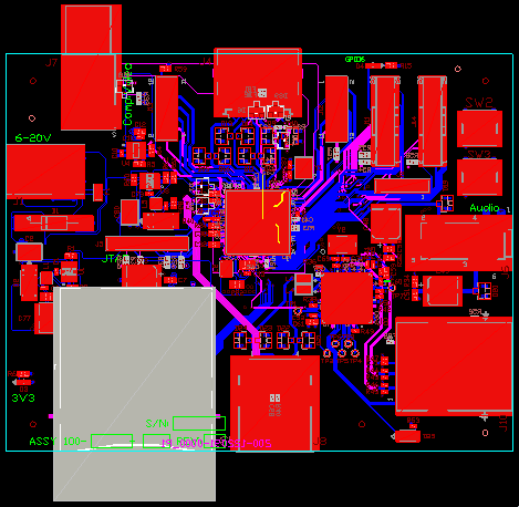
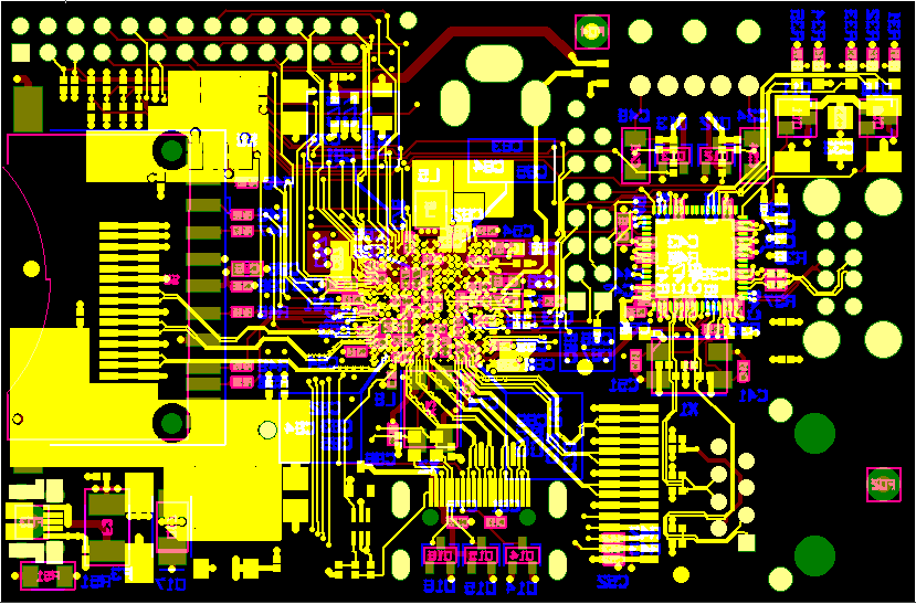
Schematic / Layout
- Official Rev 1.0 schematics PDF ]] | //www.raspberrypi.org/wp-content/uploads/2012/10/Raspberry-Pi-R2.0-Schematics-Issue2.2_027.pdf Official Rev 2.0 schematics PDF] | [[RPi_schematic_differences | differences ]] | [[RPi_schematic_errata | errata ]] | [[RPi_schematics_breakdown | breakdown ]] | [[RPi_Partial_BOM_Rev2.0_ModelB | partial BOM
Power
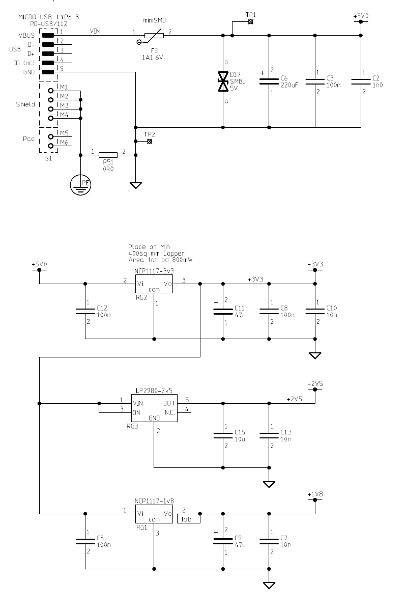
The board takes fixed 5 V input, (with the 1.2 V core voltage generated directly from the input using the internal switch-mode supply on the BCM2835 die). This permits adoption of the micro USB form factor, which, in turn, prevents the user from inadvertently plugging in out-of-range power inputs; that would be dangerous, since the 5 V would go straight to HDMI and output USB ports, even though the problem should be mitigated by some protections applied to the input power: The board provides a polarity protection diode, a voltage clamp, and a self-resetting semiconductor fuse.
Premier Farnell recommend the following power supplies:
- Model A: 5 V DC, 500-700 mA
- Model B: 5 V DC, 700-1500 mA
Power consumption of the Raspberry Pi device is
- Board A: 5 V, 500 mA (2.5 W) without any devices connected (e.g. USB, Ethernet, HDMI)
- Board B: 5 V, 700 mA (3.5 W) without any devices connected (e.g. USB, Ethernet, HDMI) (Is this correct? These ://www.raspberrypi.org/forum/troubleshooting/usb-hub-sending-power-to-raspberry-pi-through-usb-port/#p68382 links ://www.raspberrypi.org/forum/general-discussion/raspberry-pi-power-requirements/page-2/#p68224 suggest that the 700 mA is only required if “using networking and high-current USB peripherals” ://www.raspberrypi.org/archives/260.)
You will need to provide a power supply that can provide enough current to power the device plus any connected peripherals, and taking into account inefficiencies of the supply itself and the cable between the power supply and Raspberry Pi. The community advises opting for a power supply that can supply at least 1 A if using USB peripherals or Pi plates that draw more than a few tens of milliamperes of current.
- As the 5 V rail is brought out in the Rpi_Low-level_peripherals | GPIO pins, you can power the Raspberry Pi from there too. You should mind however, that those are behind the power protection circuitry, so you should provide your own.
- It is possible to power the Raspberry Pi from a powered USB hub the Raspberry Pi controls, but only on 'dumb' devices, that allow the port to supply the full current without waiting for the USB device to ask for it://www.raspberrypi.org/forum/general-discussion/power-pi-from-usb-hub-connected-to-pi. As the power input of the Raspberry Pi doesn't have its data leads connected, there is no chance for a communication loop of some sorts.
- POE (Power_over_Ethernet | power over Ethernet) is currently not available for the Raspberry Pi (but nobody stops you from taking your soldering iron and doing it yourself - mind though that the Ethernet jack on the board is a 'magjack' - http://www.sparkfun.com/datasheets/Prototyping/MagJack.pdf - which means that the usual 'dumb or passive PoE' power pins 47 and 78 are *not* wired through to the board. So this is not an entirely trivial exercise).
- Back-Powering; (powering the Raspberry Pi from a USB hub through the uplink/data port, single cable) Back powering is possible on the Raspberry Pi, but not advisable. Revision 1.0 boards have to be modified to back power, this is due to the 140 mA “polyfuses” that are installed in the USB port circuit. Revision 1.1 boards do not need modifications to back-power, they have replaced the polyfuses with 0 ohm resistors in their place. Revision 2.0 boards do not need modification, they have neither resistors nor polyfuses. It is advised that short (12“ (.3 meter) or less) USB cables be used for back-powering a Raspberry Pi. Cable resistance plus connector resistance can quickly reduce operating voltages below the proper range (5.25 V to 4.75 V). But do note that if you do not power the Raspberry Pi in the “official manner”, that is through its micro-USB port, but use any alternative way (such as through the GPIO header, the test points TP1 and TP2), but also by back-powering it, you are actually bypassing the Raspberry Pi's input polyfuse protection device! This can have extreme consequences if ever you manage to put more than 6 V on the Raspberry Pi, even for a very short period. As this causes the overvoltage device D17 on the Raspberry Pi to trigger and short the 5 V supply! Without the polyfuse limiting the current through D17, it will burn out, probably melting the Raspberry Pi's enclosure with it, (if you have any) and possibly causing a fire-hazard. It will probably also create a permanent short of the 5 V supply! So be warned, and if you use back power make sure your hub or its PSU has a fuse to prevent this from happening. If not, add your own fuse.
Power supply problems
There have been a number of problems reported that seem to be caused by inadequate power, this is an attempt to explain what is needed and the consequences of not having enough power.
The power required by the Pi will vary depending on how busy it is and what peripherals are connected.
- Running a GUI will take more power.
- The USB devices and Ethernet connection will take power.
- Running the GPU will take extra power.
This means that it's difficult to say exactly how much power is needed. People have reported current requirements of between 300 mA and 550 mA. But it could in reality take more, especially for short periods. A simple multimeter will not show short surges on the power requirement. A surge in the power requirement for a few milliseconds will not be detectable by a meter but will be enough to cause problems. If the board does not get enough power the voltage will drop. If it drops enough parts of the system will run unreliably because data can get corrupted. The USB IC runs on 5 V and handles the USB and Ethernet ports so it's likely that this will be the first thing to fail. Problems seen are unreliable Ethernet connection and unreliable operation of the Keyboard and/or mouse.
Each of the two USB ports on the Pi has a polyfuse rated at 140 mA, so any connected USB devices should draw less than this amount of current. In addition the polyfuse will cause a significant voltage drop, so that USB devices get less voltage than is available on the Raspberry Pi itself, sometimes up to half a volt less (maybe more if the fuse has recently been hot). For regular “low power” USB devices this doesn't cause a problem as they are designed to work with voltages as low as 4.4 volt. This isn't the case however with some USB devices such as Wi-Fi dongles which may need 4.75 volt, and are also known to draw more than 150 mA when configured and active. Because of the problems these polyfuses caused Raspberry Pi's produced after August 25, 2012 have the USB polyfuses F1 & F2 removed (replaced with shorts).
The microUSB input port also has a 1.1 A polyfuse (700 mA “hold current”) which may also have enough resistance (although much smaller than the 140 mA fuses) to cause a significant voltage drop on the board, even below its 1.1 A total current.
A extended explanation of the consequences of the use of these polyfuses can be found here Polyfuses explained
There are several reasons why the power to the board may be inadequate:
- The PSU may not deliver enough power. Although the maximum power requirement is said to be 700 mA, that is with no peripherals connected (USB, Ethernet etc), so a 1000 mA PSU should be regarded as a minimum. This allows some leeway in case the power supply cannot deliver its full power without the voltage dropping.
- The PSU is not regulated.
- The cable connecting the PSU to the Pi may not be good. People have reported cables with 4 ohms resistance on the power connections. At 500 mA drain this would reduce a 5 V supply to 3 V.
- If the PSU is unregulated it can also output too high a voltage, which may trigger the overvoltage device in the Raspberry Pi, which will temporarily short the 5 V to ground, this will then “blow” polyfuse F3, which will take several days to recover from. Meanwhile (possibly with another PSU) the Raspberry Pi might not get enough power because the (partly) blown polyfuse is consuming some of the power. The solution is when this happens to ways a few days to give the polyfuse time to recover before attempting to use the better PSU. If you suspect a blow polyfuse, measure the voltage across F3, which should be less than 0.05 volt.
How can I tell if the power supply is inadequate?
Common symptoms of an inadequate power supply are
- Unreliable Ethernet or keyboard operation, especially if it's OK at first but not when the GUI is started.
- SD card errors at start up seems to be another symptom of poor power.
If you think you have a problem with your power supply, it is a good idea to check the actual voltage on the Raspberry Pi circuit board. Two test points labelled TP1 and TP2 are provided on the circuit board to facilitate voltage measurements.
Use a multimeter which is set to the range 20 volts DC (or 20 V  . You should see a voltage between 4.75 and 5.25 volts. Anything outside this range indicates that you have a problem with your power supply or your power cable, or the input polyfuse F3. Anything inside, but close to the limits, of this range may indicate a problem.

| 400px

| 250px
Things that can cause problems
- A USB connection on a TV or PC. The USB power supply specification is for up to 500 mA and if the TV implements this then it can cause problems. The system may work initially but be unreliable because as it becomes more active the power requirement increases.
- A single supply from a powered hub. Most hubs seem to deliver more than the specified current but there's no guarantee. Check the power supply rating, it must be enough to supply everything that's connected to the hub.
- A power supply that is rated for less than 700 mA may work some of the time.
- Adding a USB hard disk drive. A HDD will take quite a lot of power as it starts, maybe an amp or more. It the power supply for this also supplies the Pi then this could overload things and cause trouble.
- Some complex keyboards have been reported to take a considerable amount of power, maybe up to 500 mA. The Pi cannot deliver this amount of power. Simpler budget keyboards may be better. If the system works with no keyboard attached but not with a keyboard then it's worth trying a different, simpler, keyboard.
Summary
- If you are having unreliable operation the first thing to do is check your power supply.
- Start with a good quality regulated power supply that is rated to provide 5 V and at least 1 A (1000 mA).
- Use a good quality micro USB cable. Cables are notorious for giving trouble so be prepared to swap for another one.
- Not all power supplies will deliver what they claim.
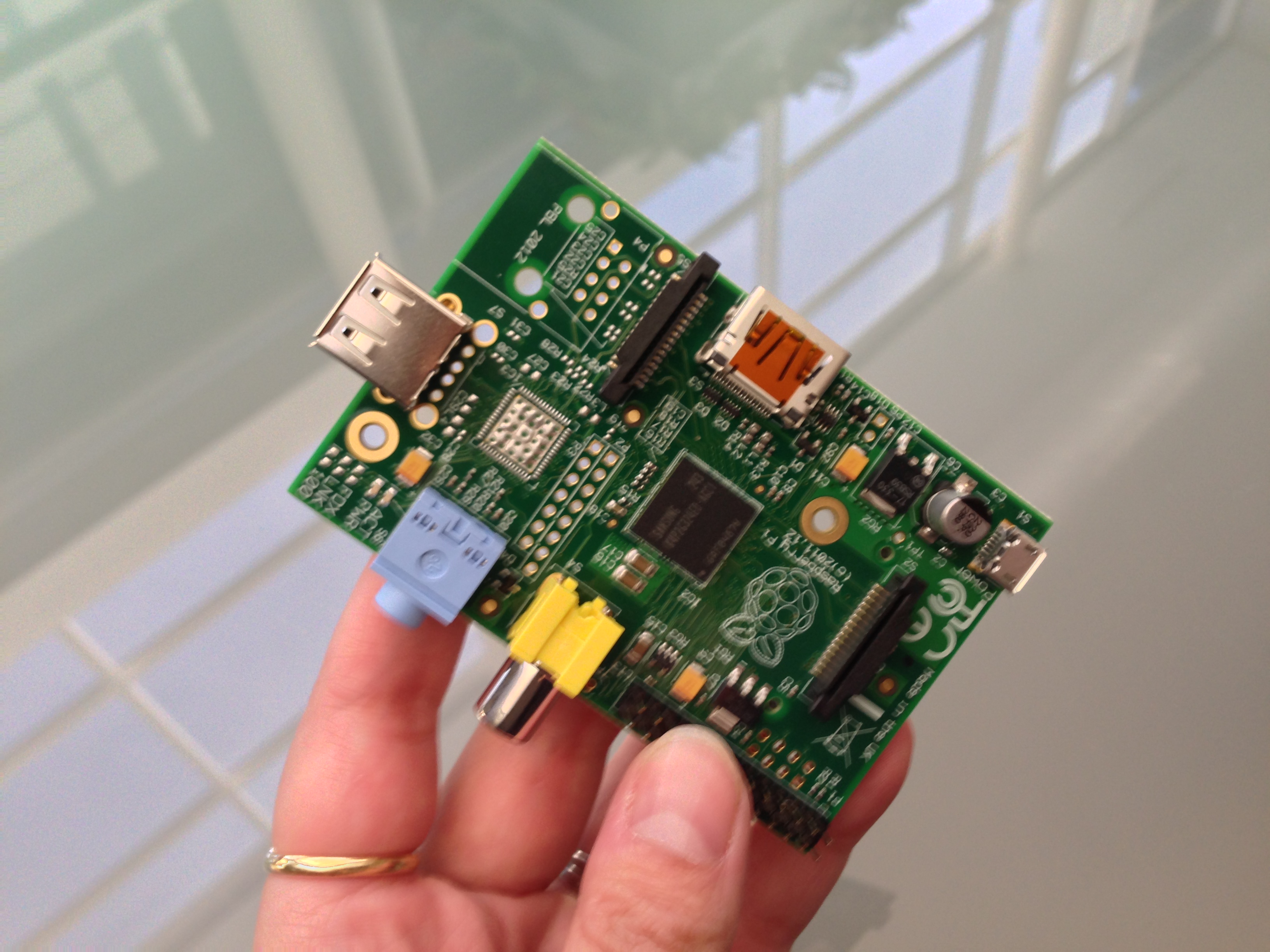
Capacitor C6
Behind the microUSB power connector on the Model B is a metallic grey component called a capacitor, marked as C6. This capacitor helps stabilise the DC power on the board, but for some it has also become a place for their thumb when removing the Raspberry Pi's power lead; unfortunately, this can result in the capacitor breaking off! It has been stated in the forums that the type of capacitor used for C6 will be changed on later Raspberry Pi models for one with sturdier leads. If you do break off your C6 capacitor, it's highly likely that your Raspberry Pi will still work properly, unless you have a particularly unstable power supply, but the general advice is to not use C6 as a leverage point when removing the power connector and also take care when storing or transporting your Raspberry Pi if it's not fitted in a case - try not to stow the board where C6 could be knocked by other items - for example in a laptop carry case or in amongst some books.

| 300px | thumb | center | Capacitor C6 (ringed)
It's unlikely that replacing a broken off C6 capacitor will be covered under warranty, but fortunately they are easy to replace if you have average soldering skills, but remember that reworking your Raspberry Pi will void its warranty too. C6 is a surface mount electrolytic capacitor with a capacitance of 220 microfarad (μF) and a voltage rating of 16 volt (V). The capacitor is polarised and so must be fitted the right way round - notice the black marking on one side in the picture above. A replacement capacitor can be purchased from numerous sources - for example:
://uk.farnell.com/jsp/search/browse.jsp?N=202457+110114112+110119850+110141127+110200576&No=0&getResults=true&appliedparametrics=true&locale=en_UK&divisionLocale=en_UK&catalogId=&skipManufacturer=false&skipParametricAttributeId=&prevNValues=202457+110114112+110119850+110141127&mm=1000002] | 110114112 | 110114112,1001880 | 110119850 | 110119850,1002520 | rpi_hardware | ,1002063 | rpi_hardware | ,1002999 | rpi_hardware | //uk.rs-online.com/web/c/passives/capacitors/aluminium/ | Power Supply construction - HowTo
References
<references/>